Setup of the Turbo400 with trigger guard mount
When you order a high-volume unit with the Turbo400 trigger guard mount, you get a lot of parts in the box and it can be confusing to set it up correctly. This article should help clarify how to set it up and get you mapping!
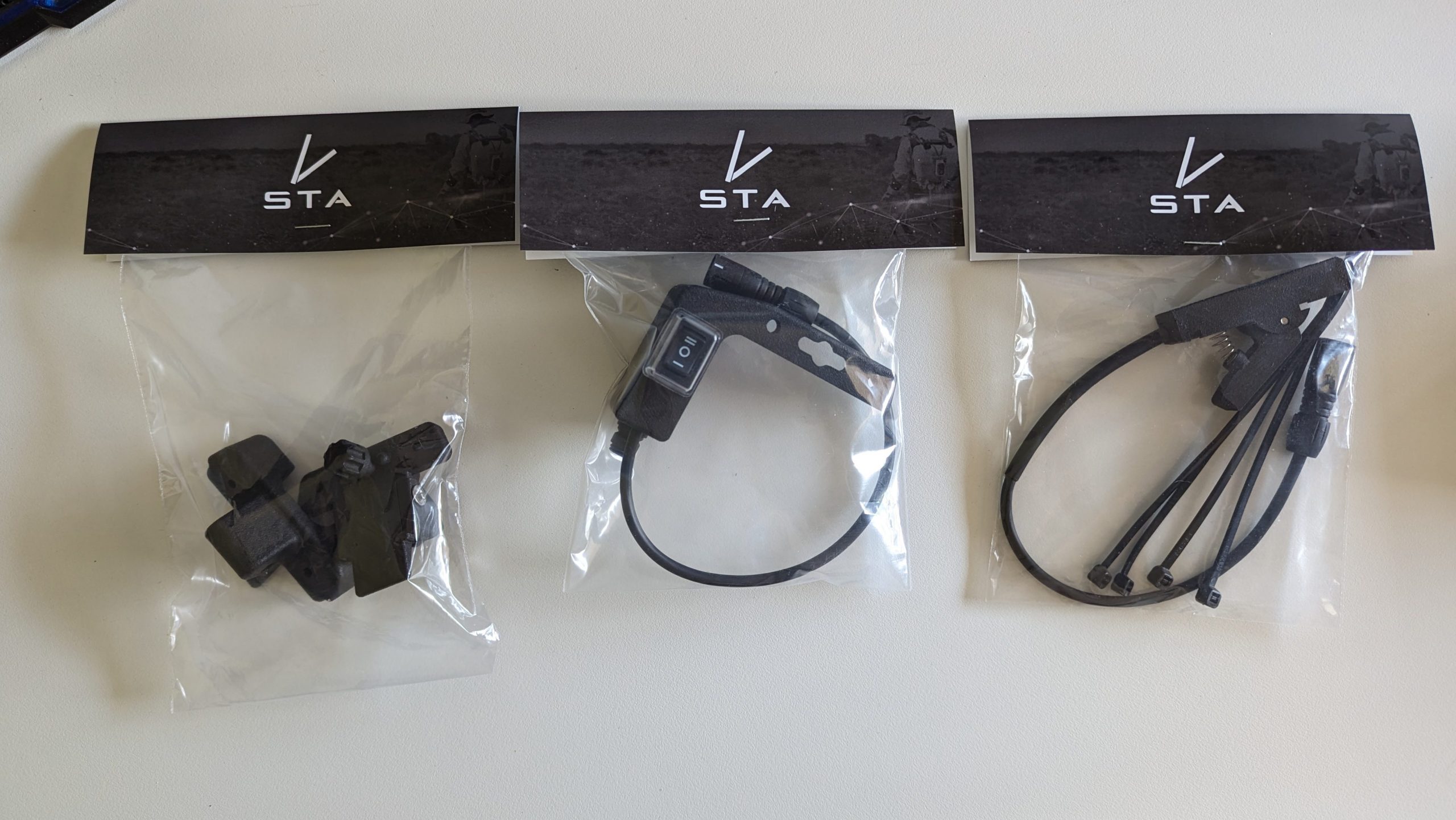
Unboxing
There are three key accessories you will get in the box. From left to right, they are, the trigger guard mounts, the 3-way switch and the trigger.
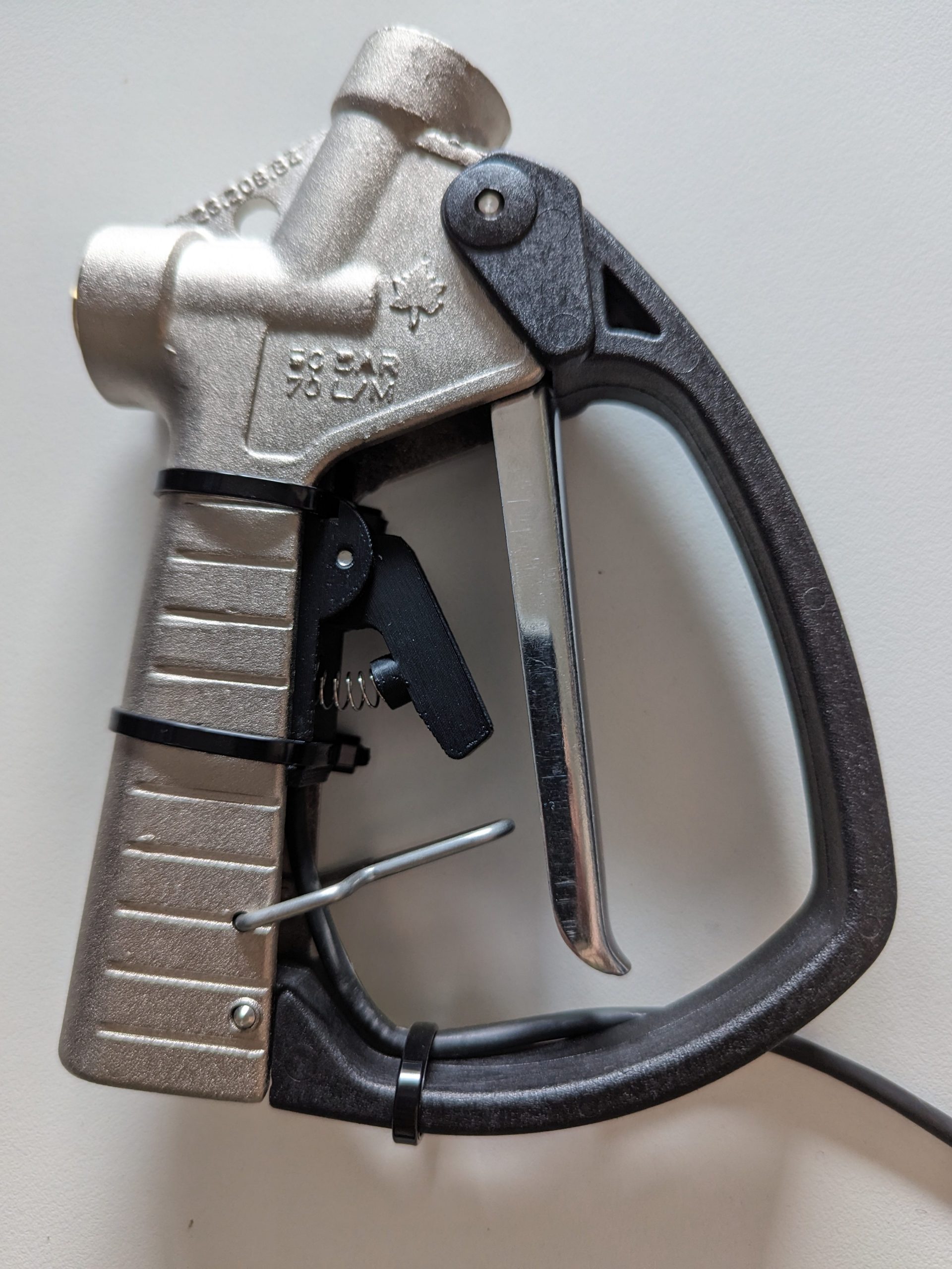
The trigger
First, setup the trigger accessory on your Turbo400 unit. Put the trigger accessory in the groove of the handle and ensure it is pushed upwards as far as possible. Then, attach the cable ties through the grooves on the trigger accessory as shown below. Consider the placement of the end of the cable ties as it may cause issues if in an awkward position.
Centre the cable and add an extra cable tie at the bottom to ensure the Turbo400 trigger does not pinch the cable when pressed.
Attaching the trigger guard mount
Next, attach the mounts to the trigger guard. The bottom one requires a cable tie through the hole seen below.

The top one needs to be bolted on. Remove the bolt from the mount accessory, and slide the mount into the groove of the Turbo400 handle. Then place the plastic part back on and bolt it on.


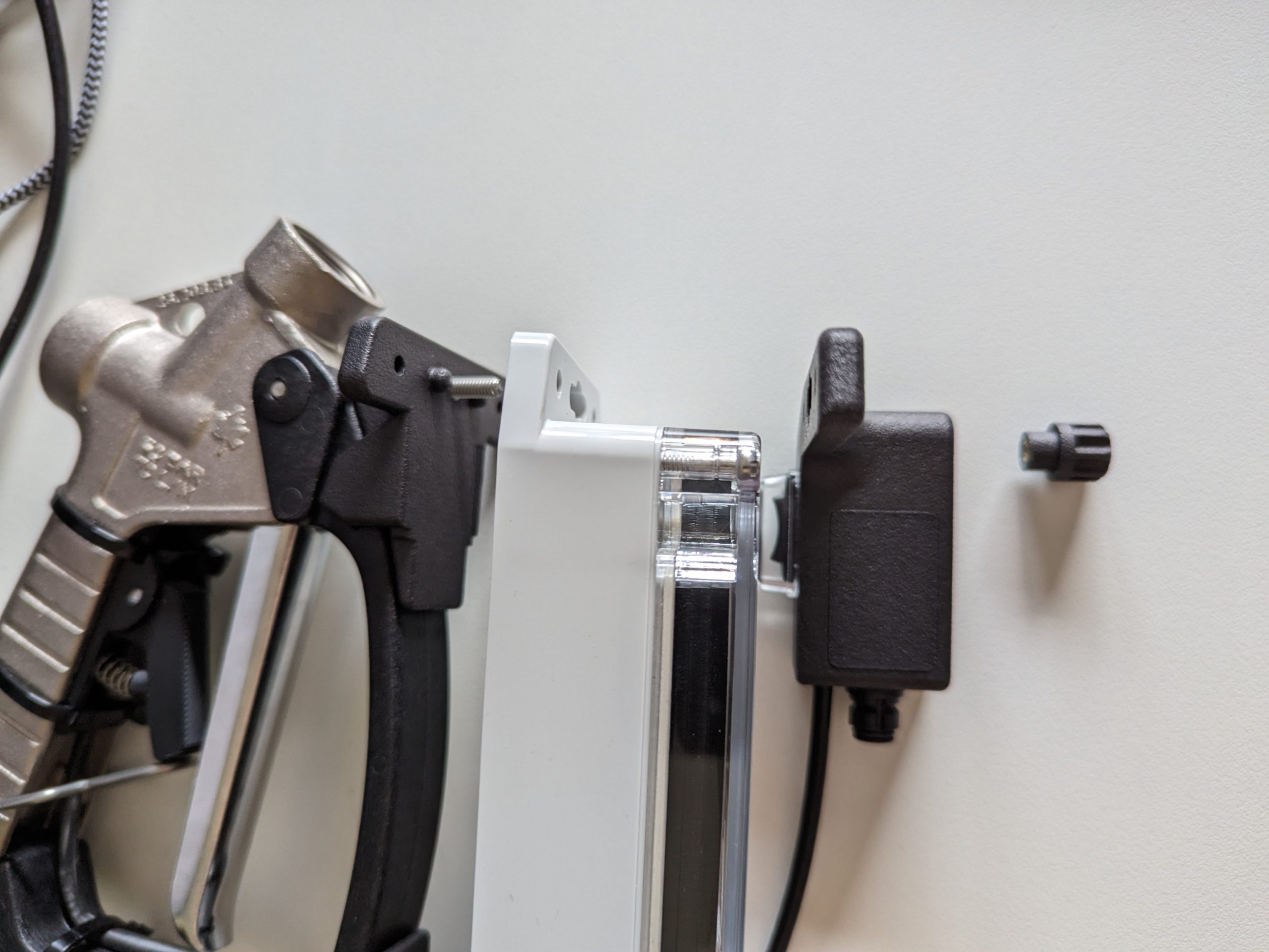
Attaching the mapping unit to the trigger guard
Below is the order of attaching the accessories. Note that the 3-way switch is facing towards the handle, so the operator can see it when in use. The 3-way switch is optional and can be left off if it is not required.
Insert the mapping unit into the bottom mount. It should clip in.
Then bolt the mapping unit and 3-way switch to the mount.

The view from the operator, when in use.
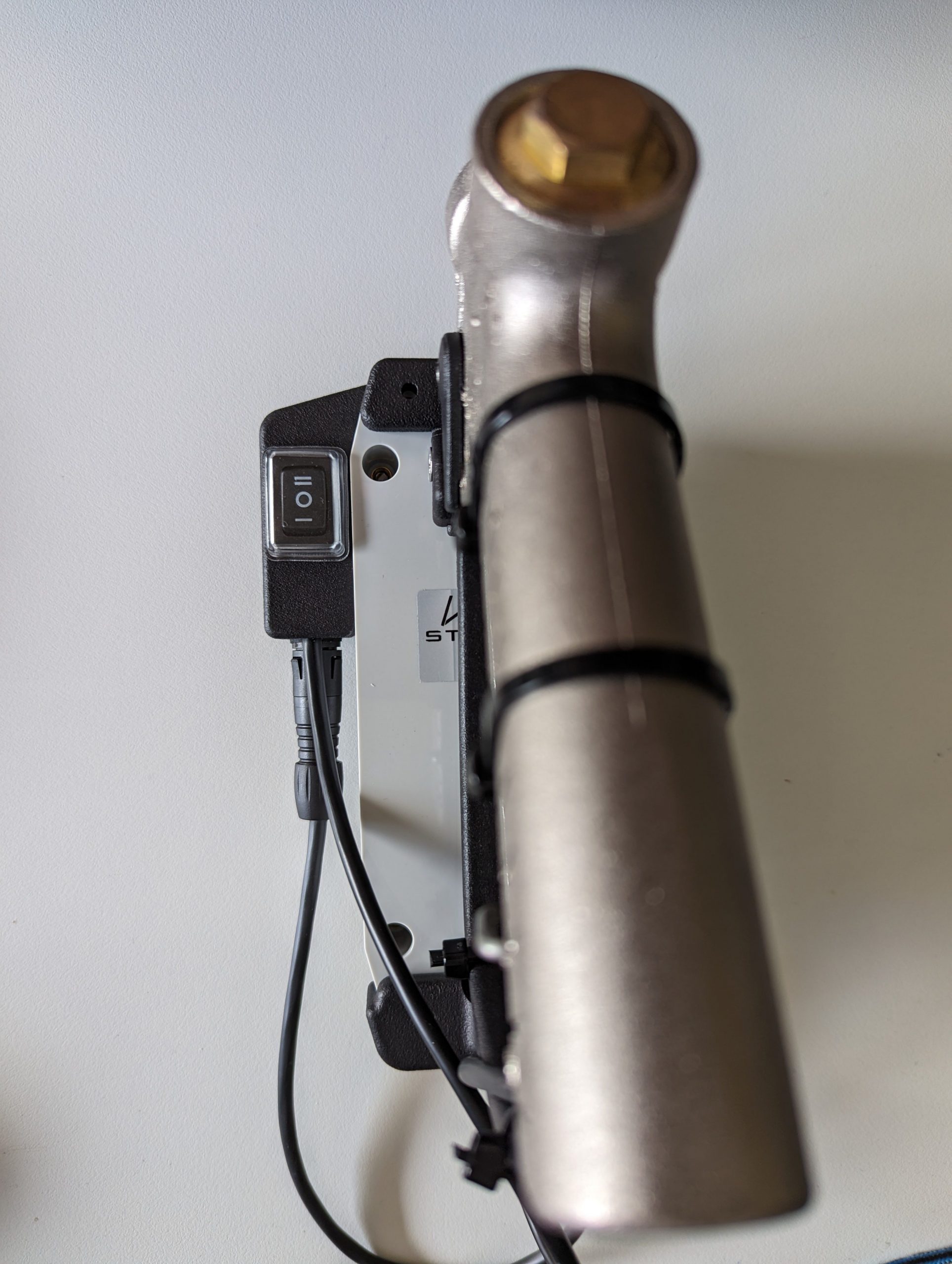
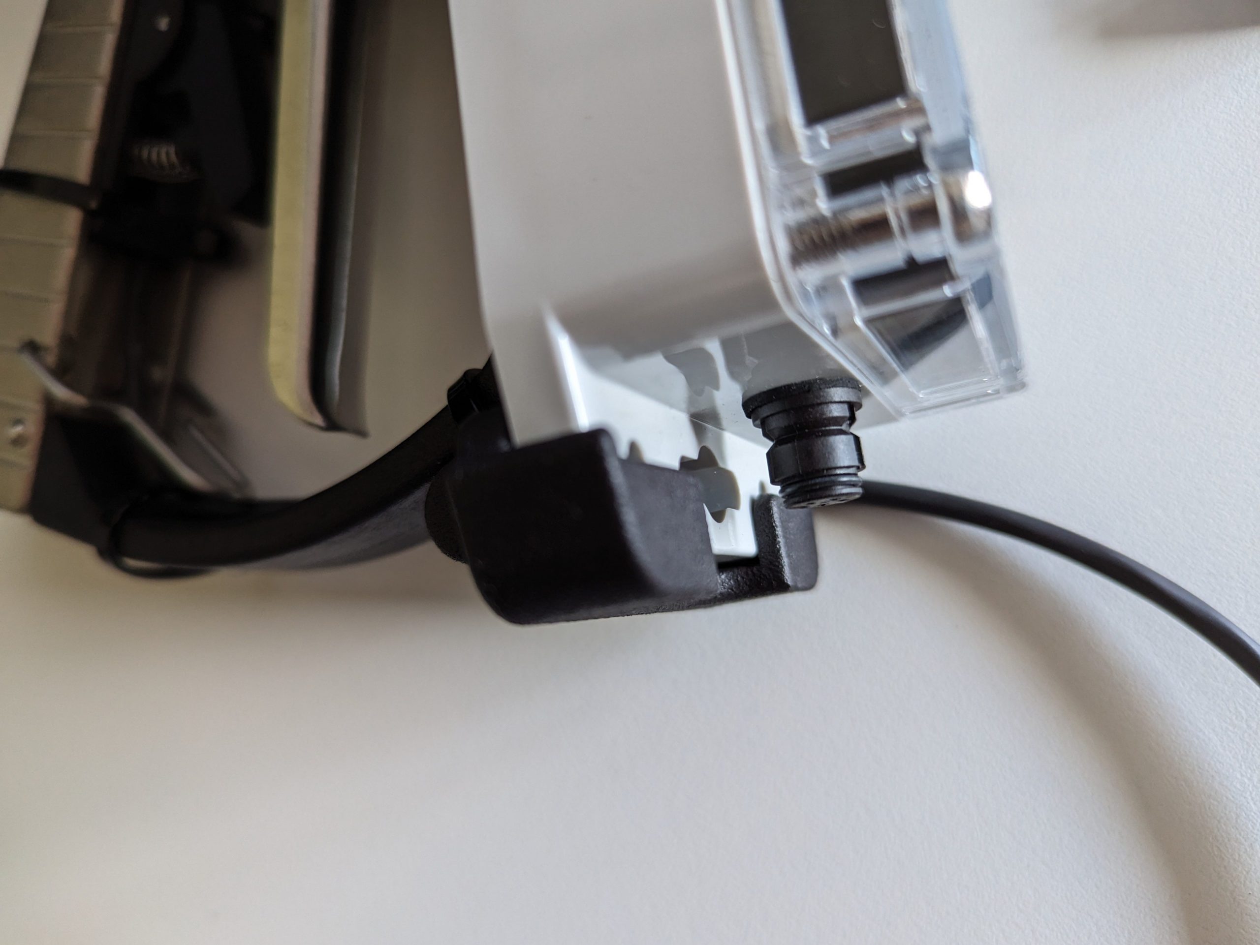
Plug them in
The trigger accessory plugs in to the 3-way switch. The 3-way switch plugs into the mapping unit. It is done this way so that the 3-way switch can be bypassed if it is not required, simplifying setup.

If you have any problems, reach out to support.
Recent Posts

STA onboarding
Read More »
So, why the STA logger?
Read More »
Post processing STA Explorer HA data
Read More »
Accurate tree planting mapping – Using the STA explorer HA
Read More »